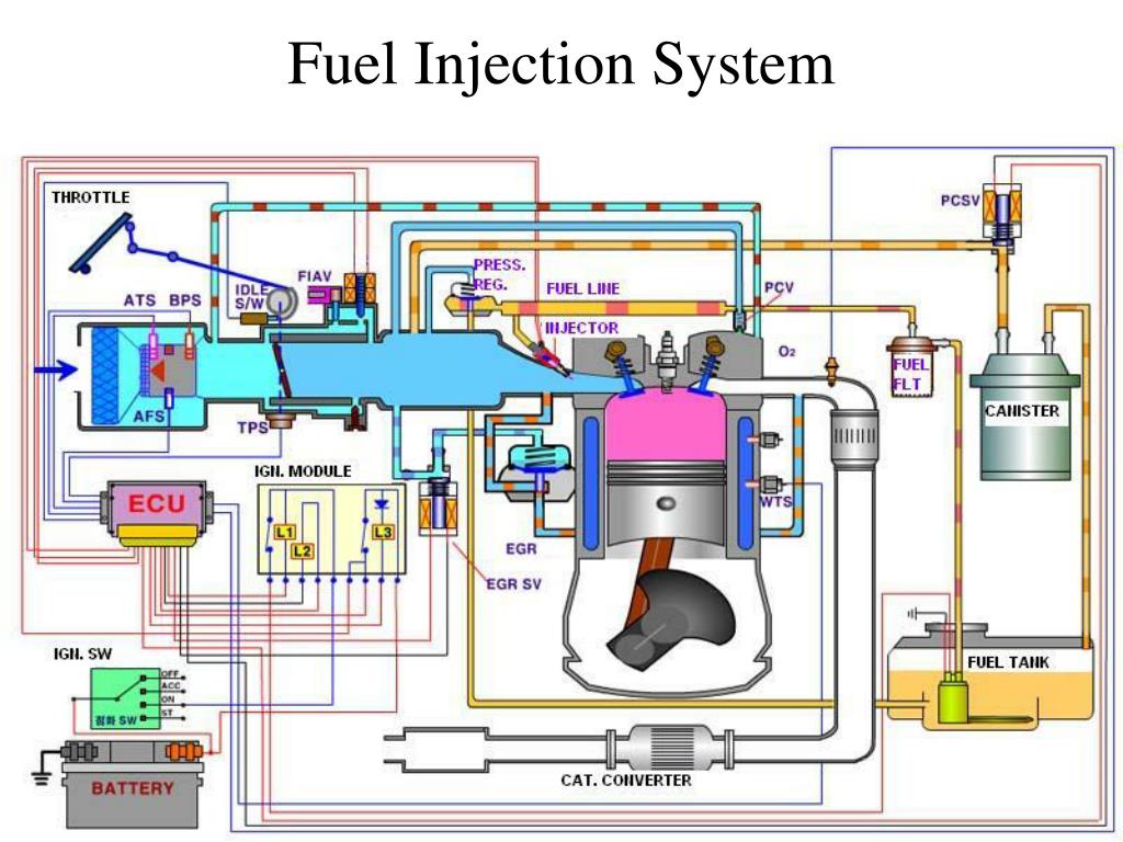

Solid injection systems can be classified into Īll the FI systems comprise of following components: Solid Injection system : Liquid fuel is injected directly into combustion chamber. Air Injection system : Fuel is forced by means of compressed air. No lag during beginning and end of injection to eliminate dribbling of fuel droplets into the cylinderĪir Injection system and Solid Injection system To supply equal quantities of metered fuel to all cylinders in case of multi cylinder engines. Uniform distribution of fuel droplets throughout the combustion chamber. Proper spray pattern to ensure rapid mixing of fuel & air Proper atomization of fuel into fine droplets Proper control of rate of injection to achieve desired heat release during combustion without knocking. Performance power, fuel economy, emissions Precise timing of fuel injection in the cycle to ensure Accurate metering of fuel injected per cycle to meet changing demand of speed & load The following requirements must be met by the Fuel Depending upon the demand requirements the fuel injection system continues toĭeliver the fuel during initial part of combustion.įunctional Requirements of an Injection Systemįor proper engine operation and satisfactory performance, Due to continued heat transfer from hot air to fuel, the fuel reaches to its self ignition temperature to ignite spontaneously It is atomized as it enters under high velocity and the droplets get vaporized Fuel is injected into combustion chamber towards the end of compression.


This system serves the purpose of initiating and controlling the combustion to meet the demand requirements.Fuel-Injection System is vital to the working and performance of CI engine.If there is deviation in any of the three values, it has to be corrected before commencing any action on the fuel pump timing.INTERNAL COMBUSTION ENGINES-II Fuel Injection System Ship’s engineer’s must check the correspondence between the load indicator position in the setting plate provided in the linkage, and the load indicator value at the local manoeuvring stand and at the remote control position when the VIT is set to “0”. Checking Load Indicator Values: The regulating fuel linkage transmits the movement of the governor output lever and determines the fuel feed to the cylinder accordingly. The eccentric shaft spring should also be regularly checked for proper operation in order to avoid any kind of breakdown.Ģ. Marine engineers must ensure that these valves are free from any obstruction or excessive play. Freeness of Mechanical Parts: The actuator of Variable Injection Timing (VIT) operates on the movement of eccentric shaft of suction and spill control valves. When working with a ship’s Main Engine, which is equipped with Variable Injection Timing (VIT) device, a marine engineer must know the following points for smooth engine operation:ġ. Variable Injection Timing (VIT) allows to achieve maximum combustion pressure during part load operation which helps in decreasing the fuel consumption and also achieve efficient combustion in the engine.īy controlling the injection timing of the fuel in the fuel delivery pump and advancing the fuel pump injection timing, VIT increases the maximum pressure in the engine.

The Variable Injection Timing (VIT) function of a marine diesel engine comes into play during load dependent adjustment of the combustion pressure.


 0 kommentar(er)
